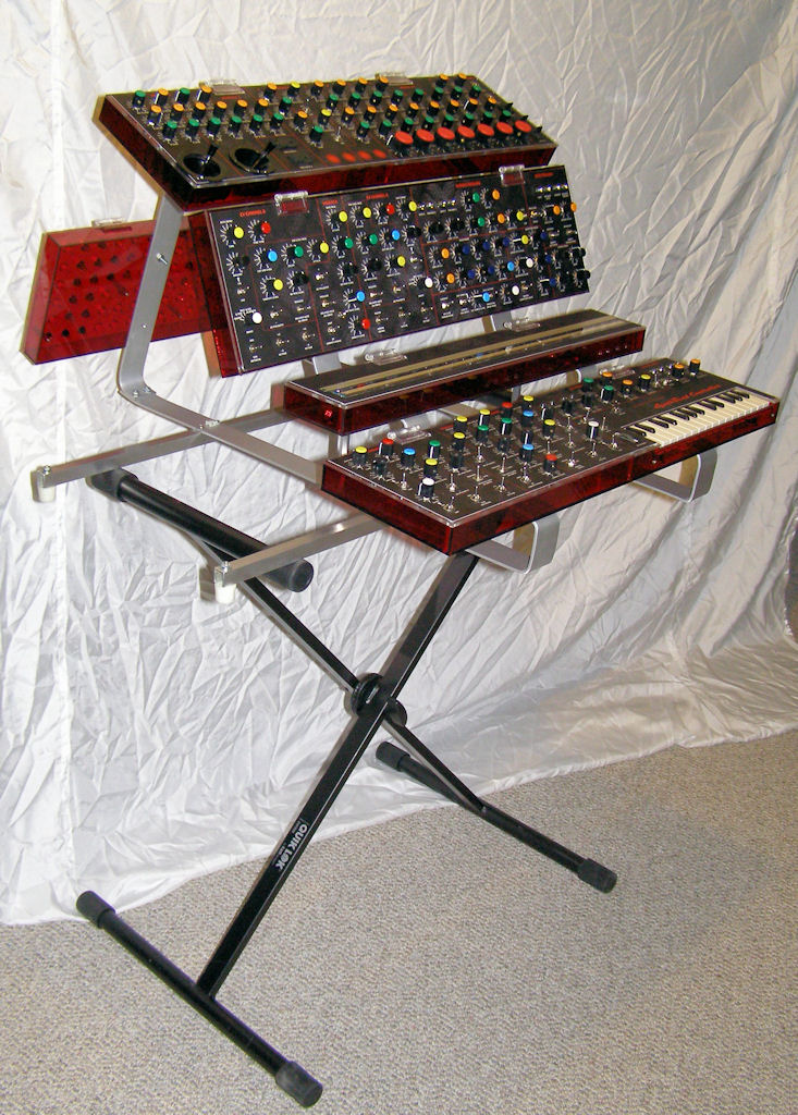
A comprehensive analogue controller for the SynthCase system
Seeing the panels all populated with controls is exciting! It's hard to wait for it to be completed so that it can be used with the SynthCase system!
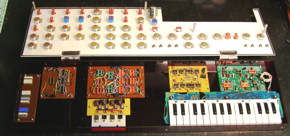
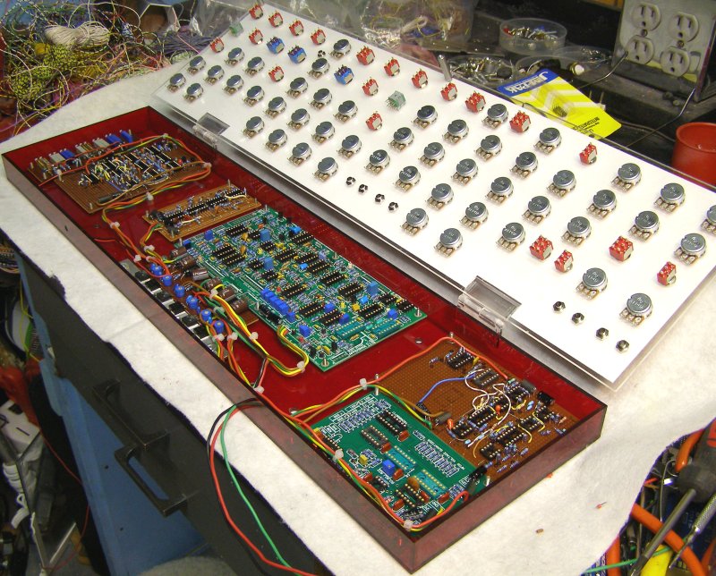
In this picture all of the keyboard module pcbs have been mounted into the case, as well as the keyboard itself. On the left hand side is a trimmer potentiometer board, with holes in the case to allow all of the CV calibrations to be adjusted from the outside. The next pcb has trigger and gate buffers as well as the channel A and B AD/AR generators. The third pcb from the left has most of the channel A and B CV processing circuitry as well as the vibrato oscillator and AD/AR generator circuits. In front of that is the voltage regulator pcb and heatsink assembly. The next pcb to the right contains the FSR circuits as well as the gate and trigger delay circuitry. Finally on the far right is the MFOS single-bus keyboard pcb.
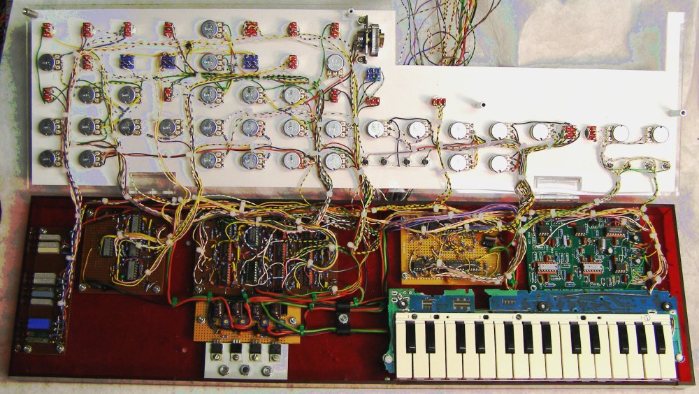
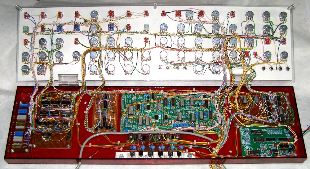
Here is a view of the keyboard module completely wired up and tested. Getting all of those parts and wiring to fit into the small case was a real challenge!
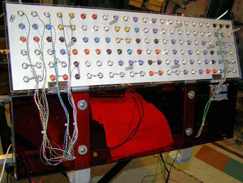
This is the rear connector module with the CV mixer circuit pcb installed.
And here is the same module with the keyboard module wiring completed:
Below is a video of the keyboard module connected to the SynthCase system showing some of it's features:
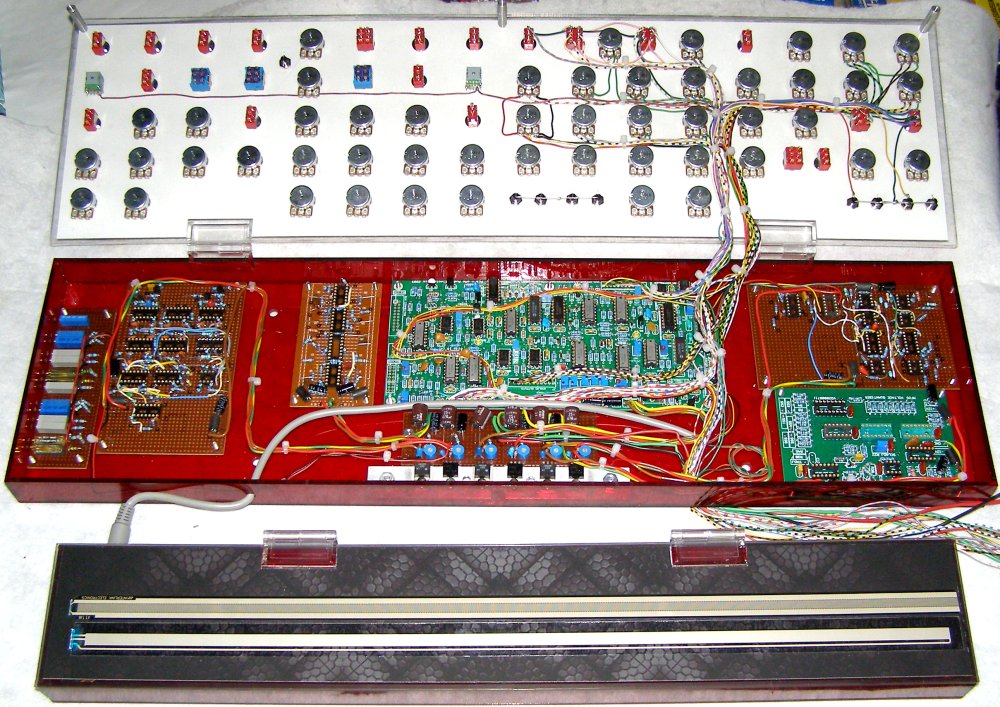
Next comes the Appendage ribbon controller and associated circuitry. Below is the module with all of the pcbs in place and wired to the voltage regulator pcb. On the front right is the MFOS quantizer pcb and behind it is the FSR, delay, and buffer pcb. To the left of that is the main Appendage pcb with the voltage regulator pcb in front of it, then the LFO circuitry pcb, then the rest of the CV processing circuitry on it's circuit board. Finally, on the far left is the trimmer potentiometer pcb, similar to the keyboard module trimmer pcb. There was not much room left over inside this module once all of the pcbs were installed!
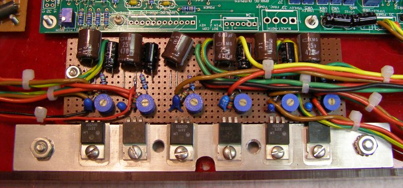
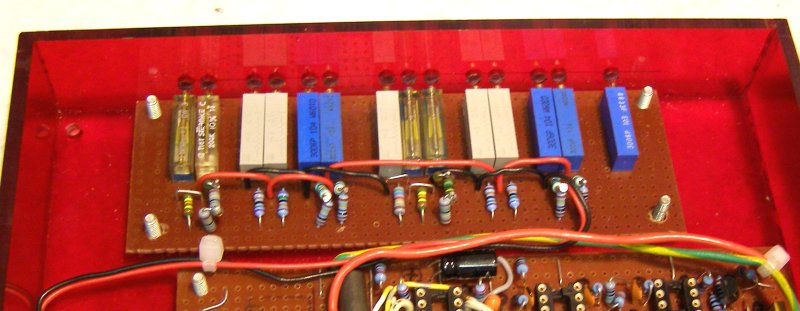
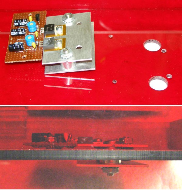
Here are some close-up pictures of the voltage regulator and trimmer potentiometer pcbs.
Here you can see the appendage board all wired up and connected to the softpot mounted on it's case. Everything so far is calibrated and working.
Below is the ribbon module with all of the wiring completed. The module is now finished except for mounting on the frame and connecting to the rear connector module.
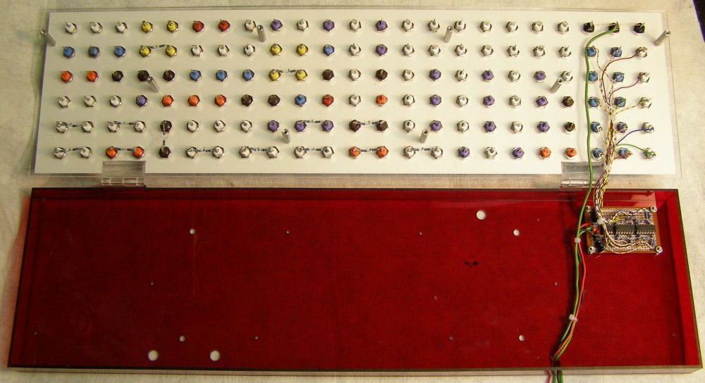
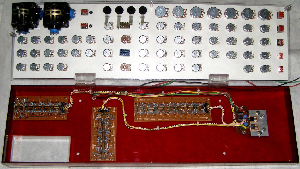
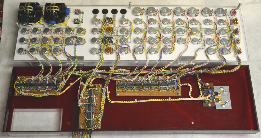
The third module with the various CV controls has the least amount of actual circuitry, however, all of that circuitry had to be built up on perfboard. Fortunately, much of it was designed using the same basic circuits repeated over and over again, simplifying construction. Here is the module with all of the pcbs installed and connected to the regulator board:
Speaking of the regulator board, below is a picture showing the heatsink design used for all of the regulator pcbs in this project. The devices themselves are attached to a piece of aluminum inside the case, which is then bolted to a second aluminum heatsink outside the bottom of the case. Thick aluminum standoffs and heat sink compound are used to conduct the heat from the inside to the outside heat sink.
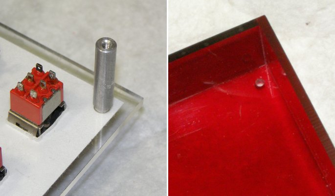
As shown below, the hinged covers for each module are held closed using standoffs at various points. The standoffs are attached to the front panels using countersunk screws hidden under the panel graphics. After the cover is closed bolts are inserted through holes in the bottom of the module to secure it.
Here is a picture of the completed wiring for the module.
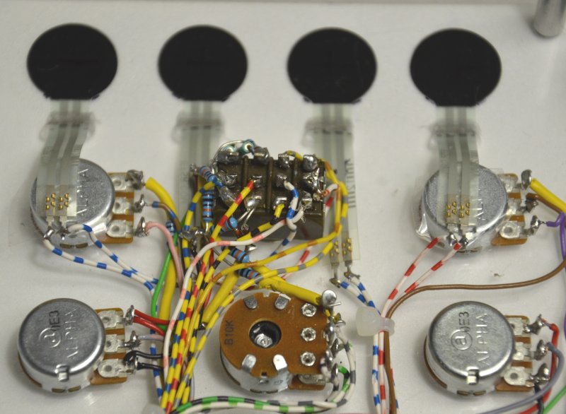
Below is a closeup picture showing the wires attached to the FSR devices. Connector sockets are normally recommended for this, but if a person is quick and careful, wires can be directly soldered to the leads of the FSRs without damaging them.
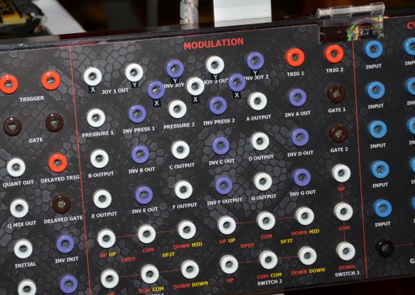
When the rear connector module was designed, it was somehow forgotten that the joysticks have TWO axis outputs, not just one! Extra conectors had to be installed to correct this error, as shown below:
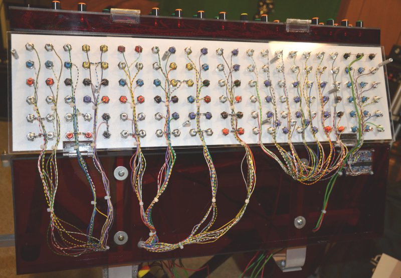
And here is a picture of all of the connectors wired up on the finished panel:
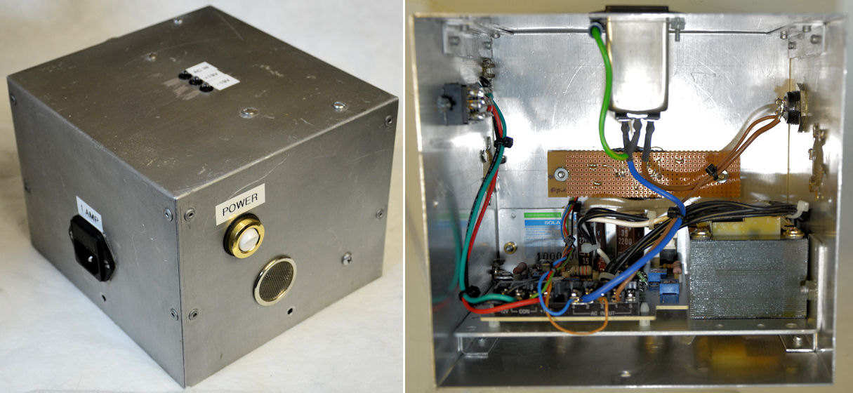
Finally we are coming to the last stage of this project, building the primary power supply. This small chassis is composed of a linear regulated power supply module, power switch, fused IEC power socket, DC output connector, and LED power monitors. The linear regulated power supply is a standard +/-15 volt type adjusted to +/-19 volts. All of the components are mounted on a salvaged aluminum metal box with a couple of ventilation holes.
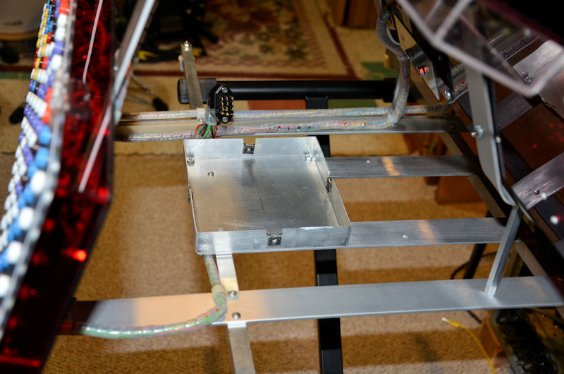
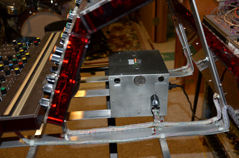
Below you can see the aluminum base that the power supply box fits over and attaches to when in place inside the SynthBend controller. The DC power connector can be seen just above it, ready to be plugged into the power supply. The wiring running between the different SynthBend modules is held in place with spiroband and p-clips, as can be seen here.
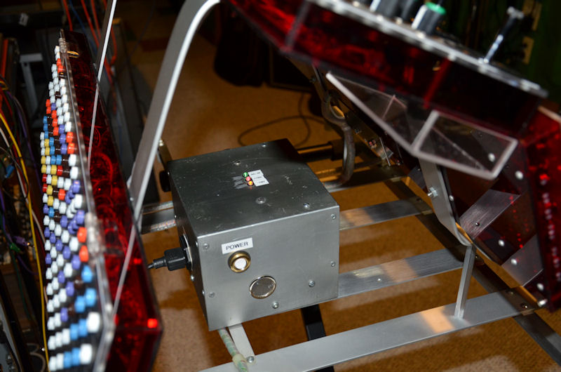
And lastly below are a couple of pictures of the power supply mounted in place and powering the system. The SynthBend controller project is now complete!
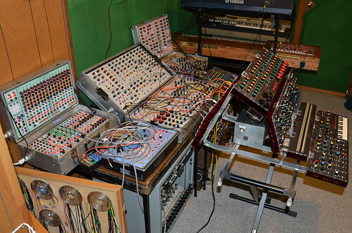
Here is the SynthBend controller all moved into it's new home connected to the SynthCase system.