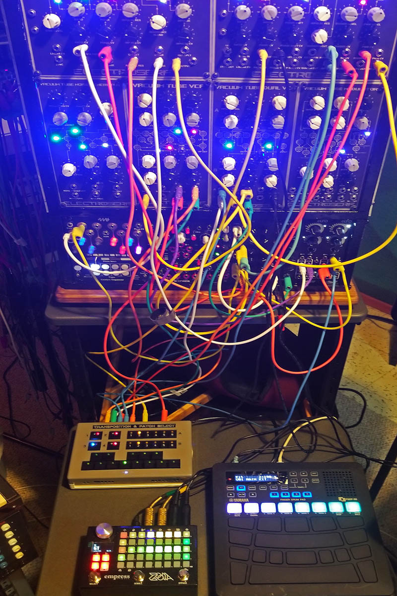
Many modular synthesizer VCOs don't have built-in octave switching capabilities, which are useful for extending the range of a keyboard. Dynamically changing keys and octaves while using a sequencer is often not an easy or ergonomic process. Unplugging and plugging cables to modify a patch while playing can be cumbersome and inconvenient as well. This project provides the capability to easily and automatically do all of those things in one handy box.
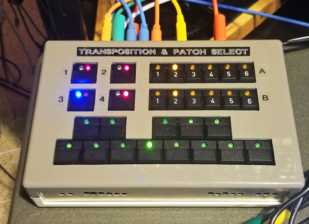
The module includes a pair of six-octave latching switch banks, a one-octave switch keyboard, and four SPDT analogue switches. There is a combined output that mixes one of the octave switch banks with the keyboard output so that they can be used together, and the keyboard has a gate output included as well, so that it can be used as a freestanding keyboard. The keyboard circuit itself is adapted from Ken Stone's CGS10 Pedal board/Mini Keyboard project. Both of the octave switches and the keyboard include a CV input for precision summing of external volt/octave signals with each switch output.
Circuit Design
All of the digital circuitry used in this project utilises discrete logic parts only, no microprocessors, so it can be built without needing any code or programming. Of course if you wanted to design one using a microprocessor chip, the circuitry could be MUCH smaller!
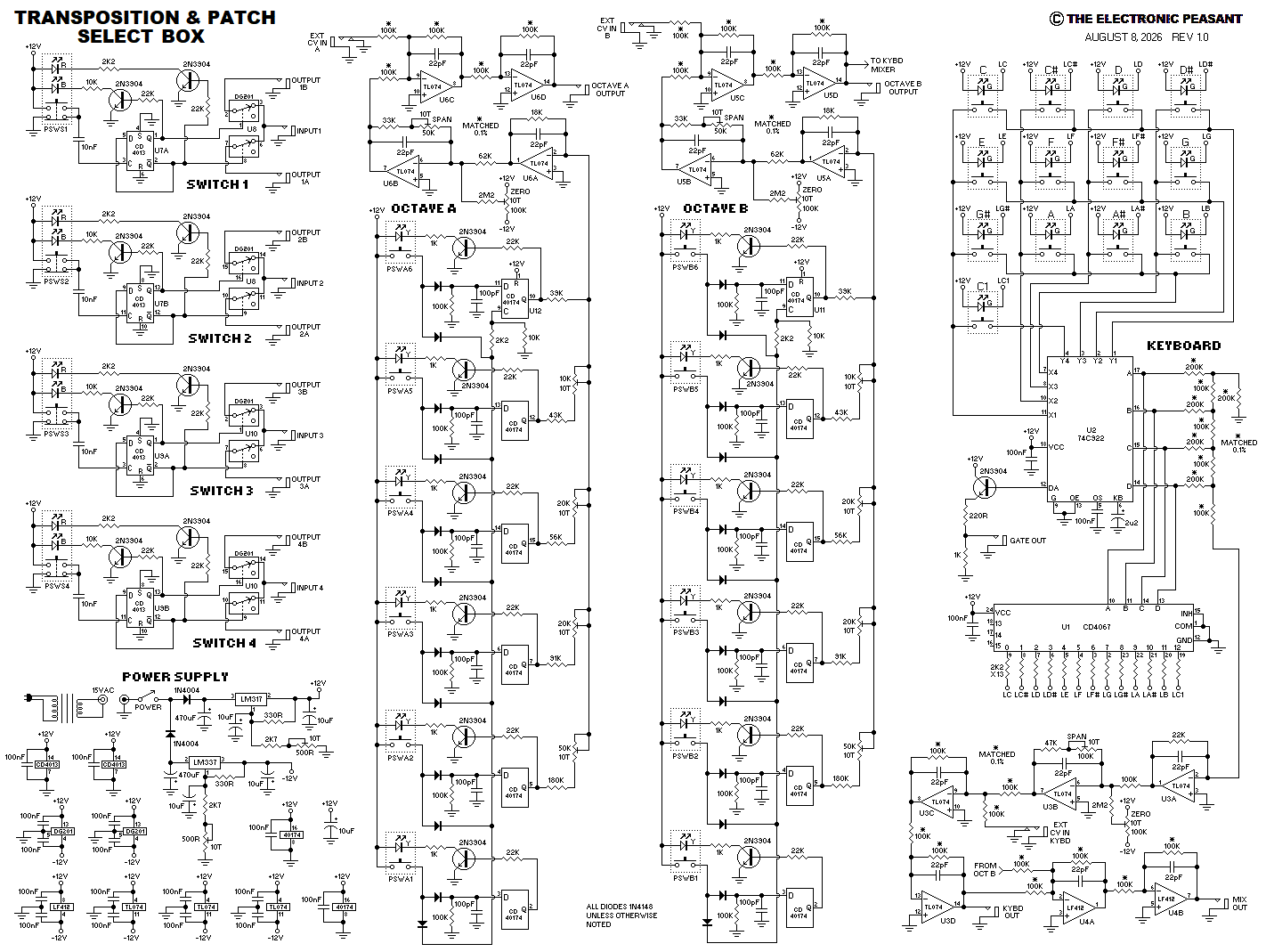
The keyboard circuit uses a 74C922 keyboard scanning IC feeding an R/2R resistor ladder and then a series of buffer circuits. The first buffer stage is for setting zero and span, the second is for mixing in external CV signals, and the final stage is for mixing the Keyboard output with the Octave B output. Using extremely tightly matched resistors within each buffer stage is required here to ensure volt/octave accuracy. A CD4067 multiplexer chip is used to decode the 74C922 output and drive the LEDs in each switch. Output current limiting resistors were not used in the keyboard and octave switch circuits, but they can be installed if anyone building this design prefers to use them.
The octave switches use CD40174 hex flip-flop ICs to latch the last button pressed and feed an adjustable resistive divider and buffer circuits similar to the ones used for the keyboard. Transistor buffers drive the switch LEDs.
The analogue switch section uses CD4013 flip-flops to latch each switch and drive DG201 analogue switch chips. Transistor buffers are used for the LEDs here as well.
The power supply uses a standard external AC output power source, driving rectifier and LM317/337 regulator circuits to generate plus and minus 12 volt rails.
Schematic Diagram
The complete schematic is shown below. Open the full-size schematic

Construction
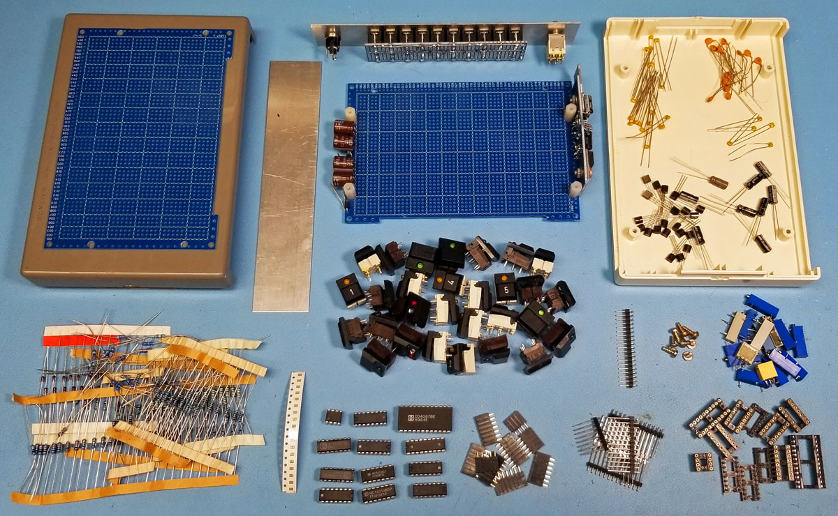
Below is a picture of the parts chosen for building the Transposition & Patch Select module. A bunch of salvaged ITT Schadow type momentary switches were chosen for the interface, since they conveniently included indicator LEDs. Next, a used plastic case was found that fit the planned switch layout and the required circuit boards. The module uses 20 jacks, and in this picture they are already mounted to a pcb and the back panel, along with the power switch and power input jack. The power supply including the two regulators is also already installed on the sides of the main pcb.
Here you can see the switch pcb fitting well inside the plastic case, with the pushbutton switch placement being determined.
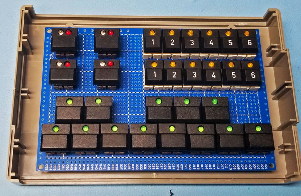
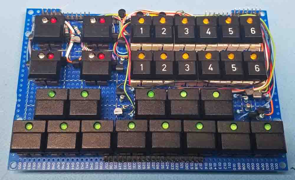
Here is the switch pcb fully populated with all of its parts, including the pin headers for connection to the logic pcb.
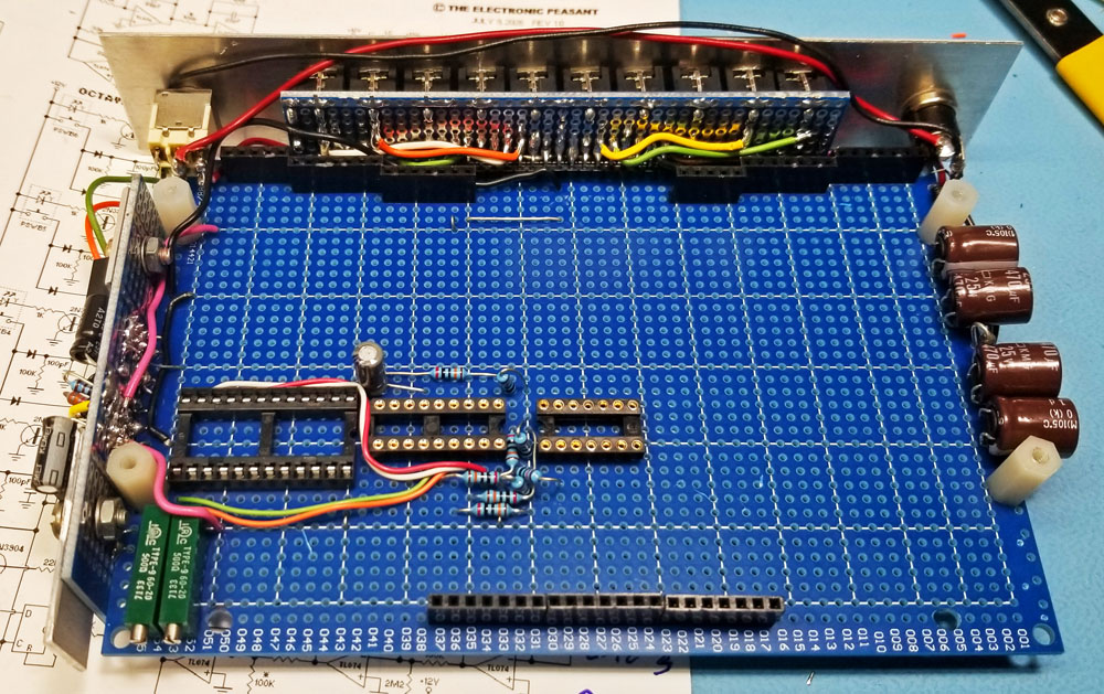
The next step is to install all of the parts on the logic pcb. Here you can see that the connector pcb, including the jacks and back panel, has been attached to the logic board via a 90 degree pin header. The female headers for connecting to the switch pcb are also in place.
And here is the logic pcb fully populated.
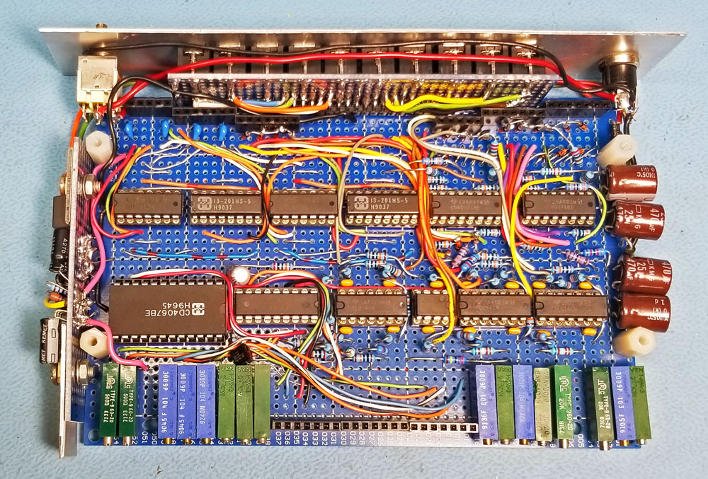
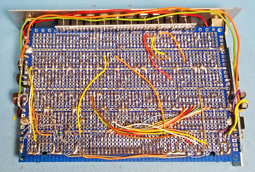
The bottom view of the completed logic pcb.
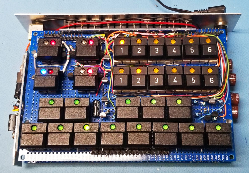
All of the electronics have now been assembled, powered up, and tested. Looking good!
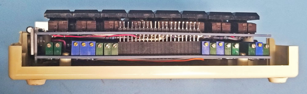
Here you can see the switch and logic pcbs sandwiched together.
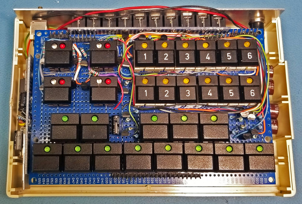
Finally everything is tucked away in the plastic case, it just needs the front panel and top cover and it's finished.
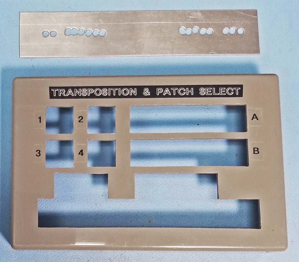
Oh wait, not quite yet. The top of the plastic case still needs to have holes cut out and shaped for each of the switches! Of course this turns out to be the hardest part of the project, with a lot of measuring, drilling and grinding. Labels were then applied to the top, and holes for accessing the calibration trimpots were cut into the metal front panel.
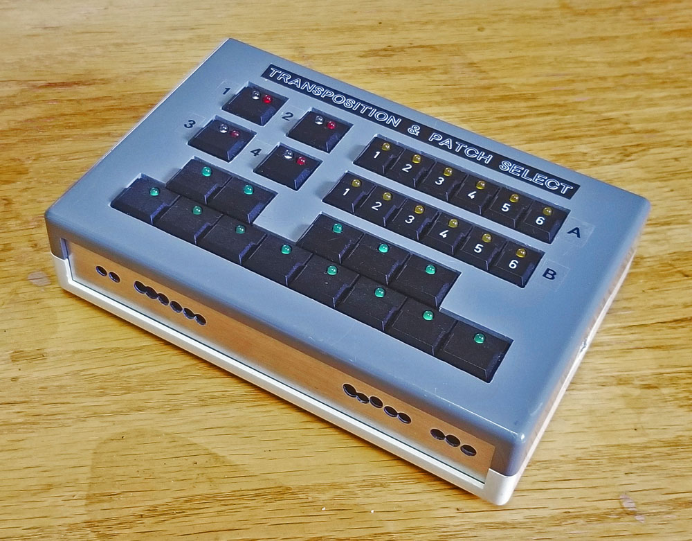
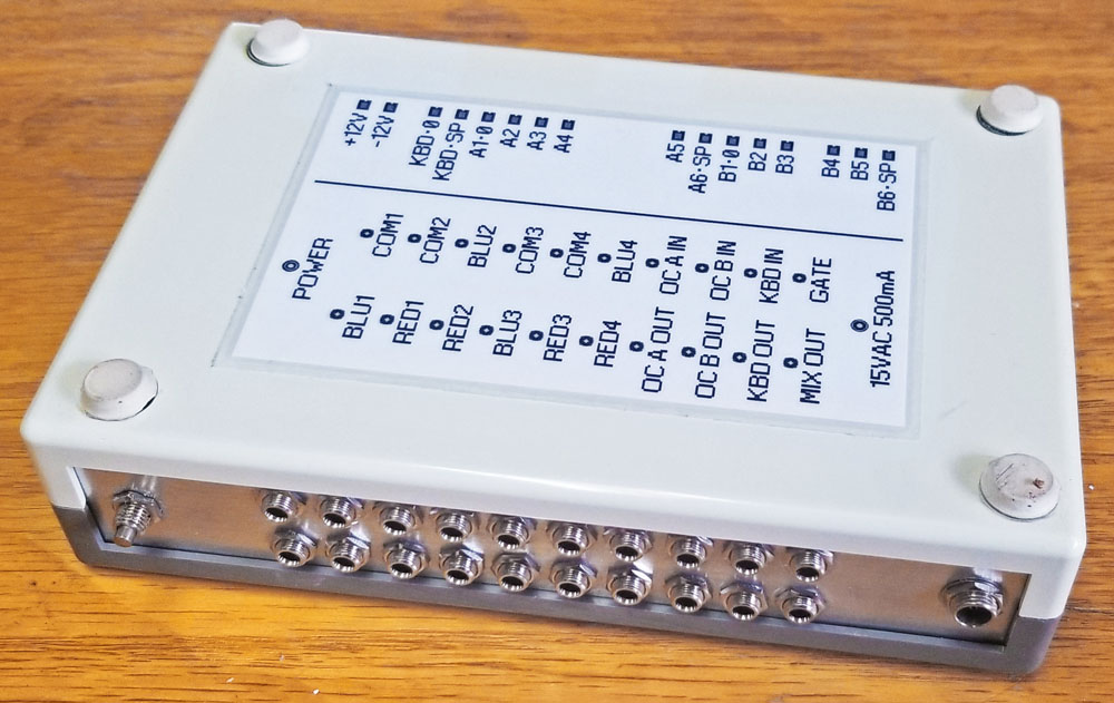
The Finished Project
And here are a couple of pictures of the finished project.
Video Demonstration
Below is a short video showing the module being used.
Results
This project was unusual in that everything seemed to naturally fit and work together without much effort. From start to finish - the size of the box and pcbs, integrating the power supply, how everything all fit together, the amount of room for everything - it was all "just right". Using the device is the same pleasant experience as well; it fits perfectly among my gear, it's convenient and easy to operate, and it works great for its intended use.